Assembly guide
Everything plugs together. No soldering. Set aside about half an hour and a couple of screwdrivers. When you’re done, head to Flash & Set Up to bring it to life.
- A #2 Phillips screwdriver
- A 2.5 mm hex key (for the M3 cap-head screws)
- Optional: a soldering iron, only if you’re using M3 heat-set inserts
- Time: ~30 minutes
- Soldering: none
- Difficulty: beginner-friendly
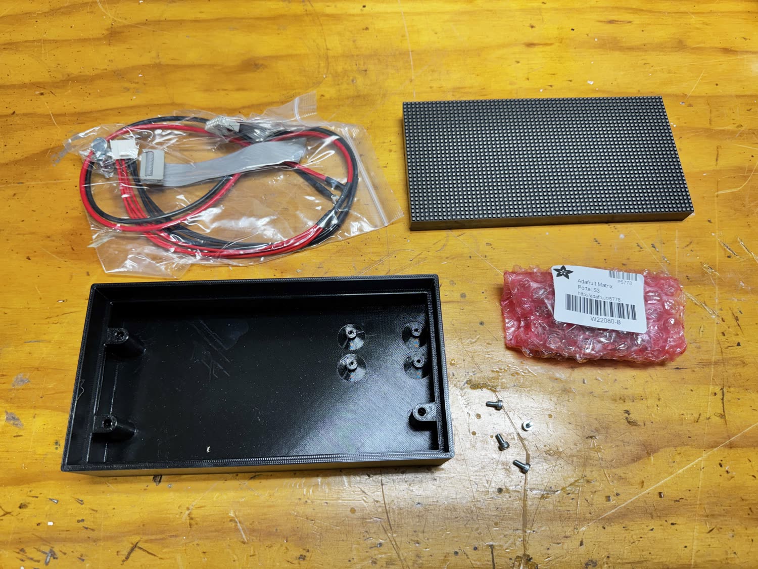
Gather your parts
Lay everything out: the Matrix Portal S3, the 64×32 LED panel, the HUB75 ribbon cable and red/black power leads (these usually come with the panel), the two 3D-printed case pieces, and your screws.
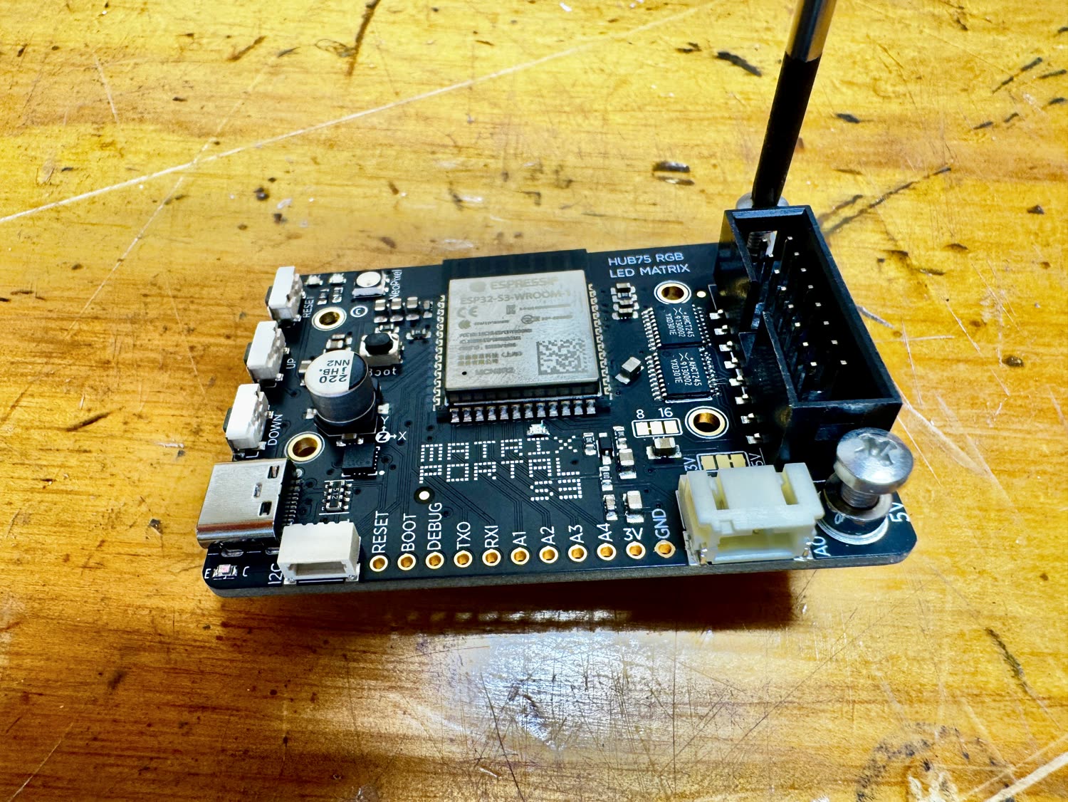
Fit the HUB75 connector to the board
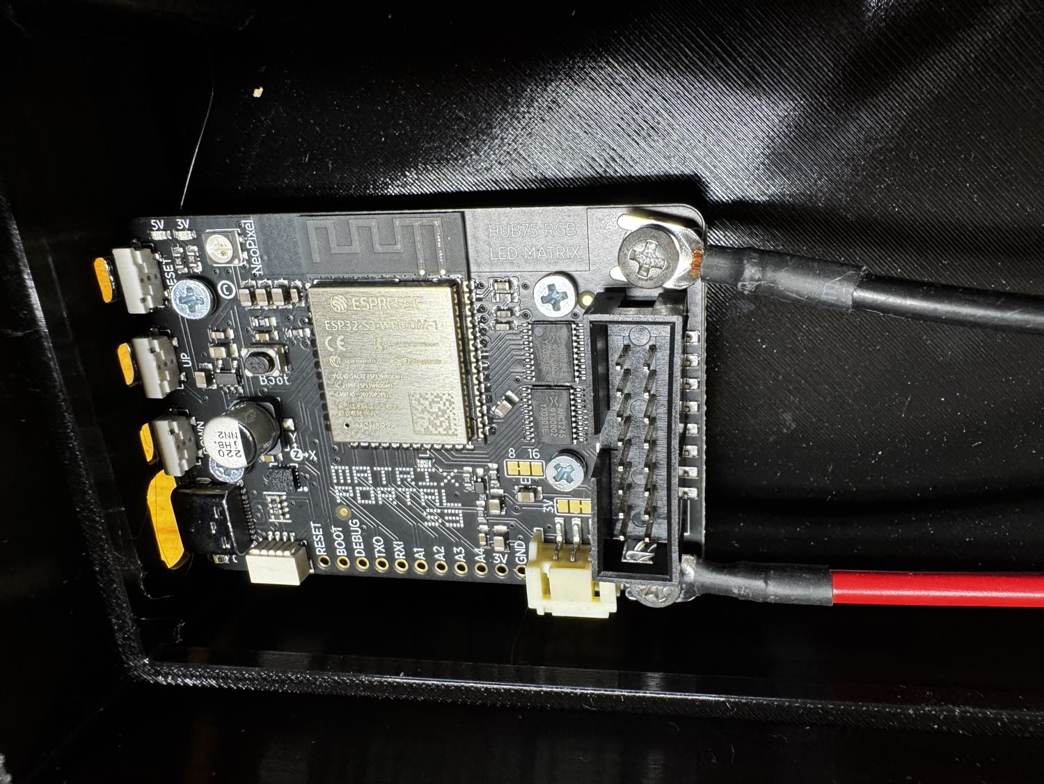
Seat the HUB75 ribbon-cable header firmly onto the Matrix Portal’s pins. It only goes on one way. The connector is keyed, so you can’t reverse it.
Mount the board in the case
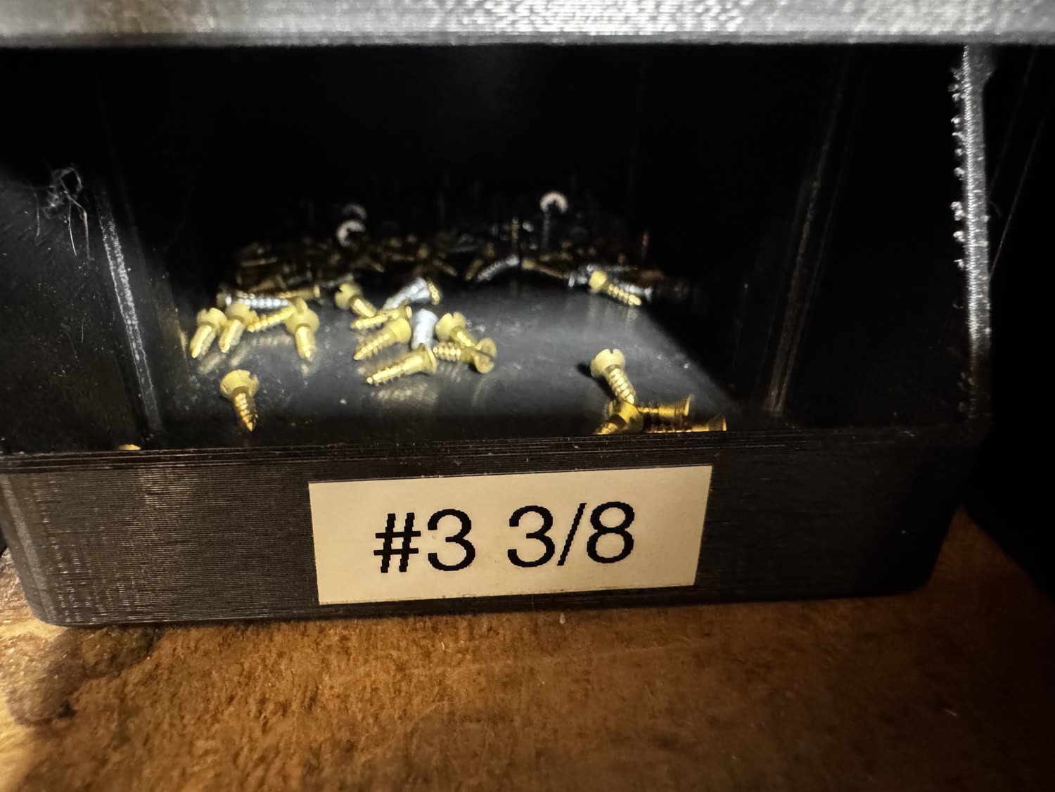
Drop the Matrix Portal into the printed body so its mounting holes line up with the four standoffs, then drive the four #3 × ⅜″ screws with a Phillips screwdriver. Snug, not gorilla-tight.
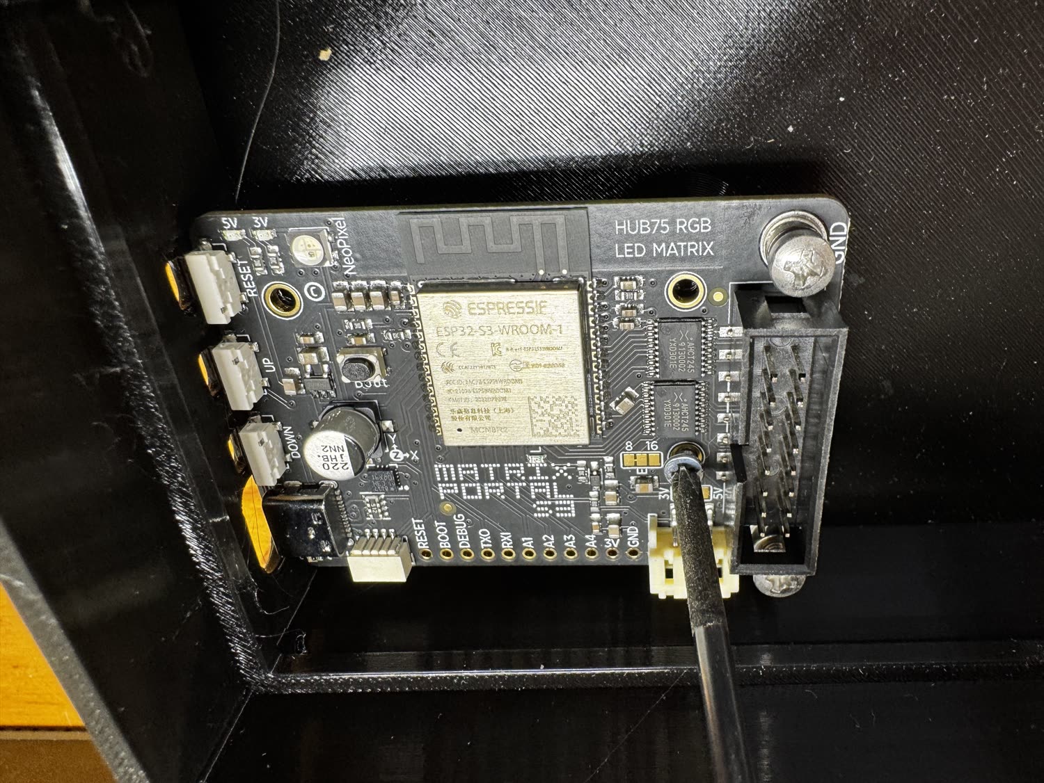
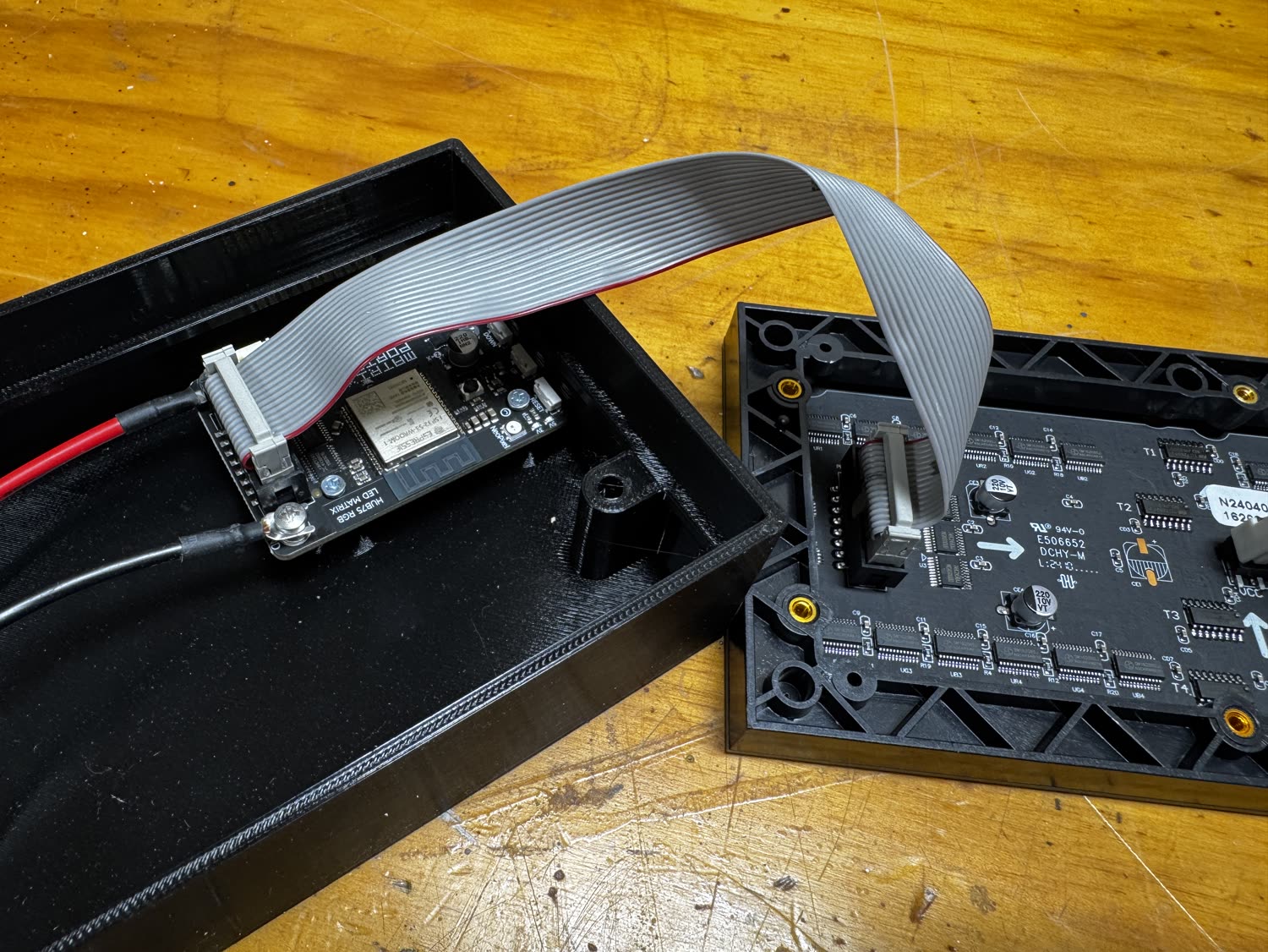
Connect the ribbon and power at the board
Plug the HUB75 ribbon into the board’s connector and attach the red/black 5 V leads. Route the cables toward the opening so they can reach the panel.
Wire up the LED panel
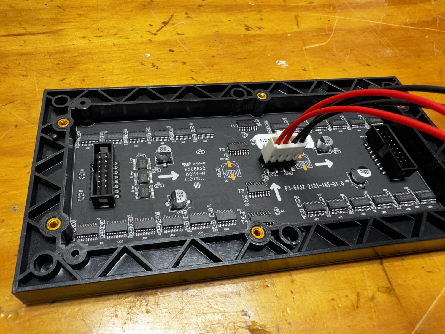
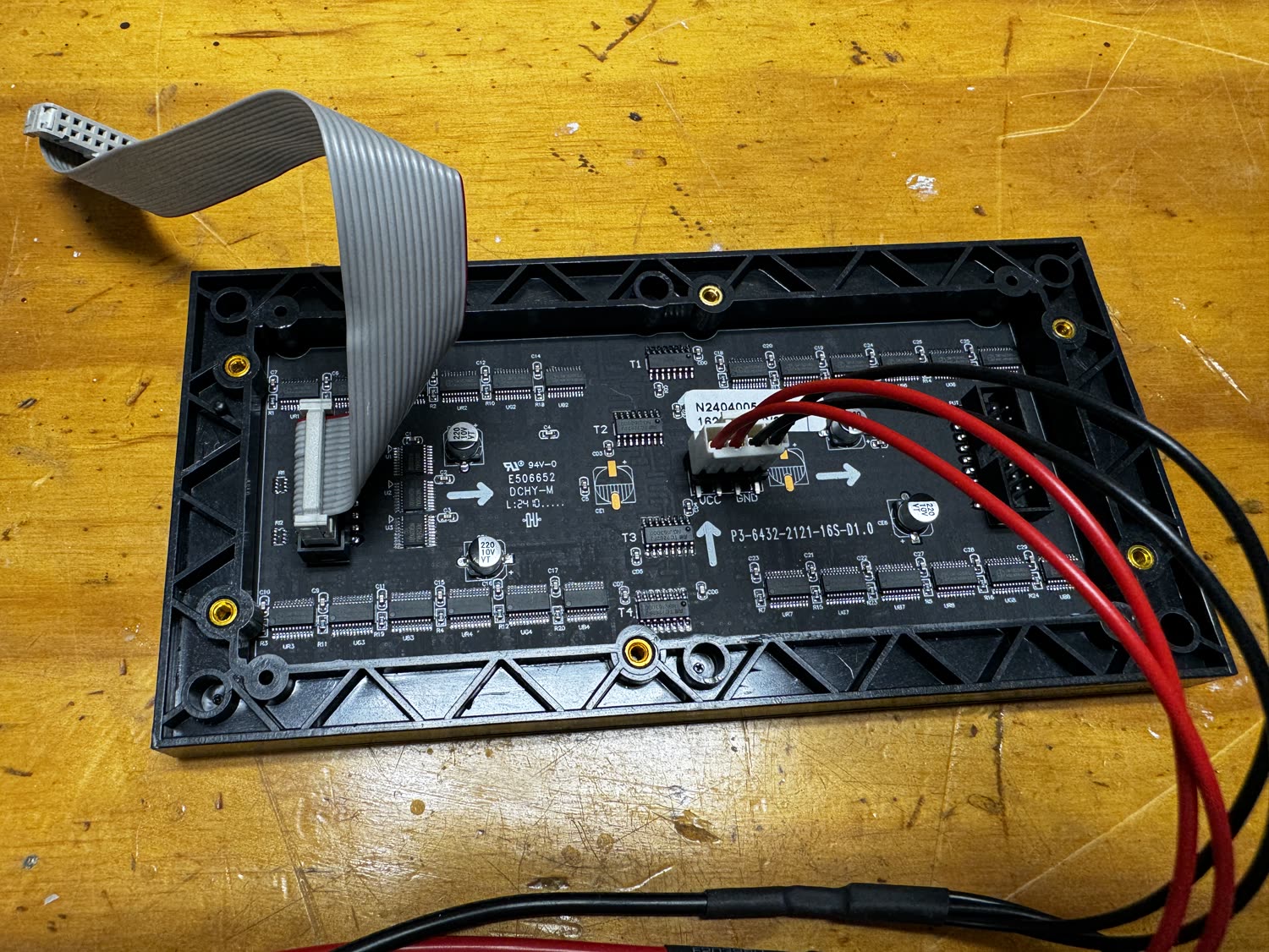
On the back of the panel (marked P3-6432, the 3 mm-pitch 64×32 module), plug the ribbon into the HUB75 input and press the red/black leads onto the panel’s power connector, matching VCC and GND.
Seat the panel in the bezel
Settle the panel into the printed front bezel so the LEDs face out through the frame. The bezel’s corner holes line up with the case for the final screws.
Join the two halves
Fold the body and the panel together, tucking the ribbon and power leads inside so nothing is pinched. Everything should sit flush.
Fit the branded faceplate
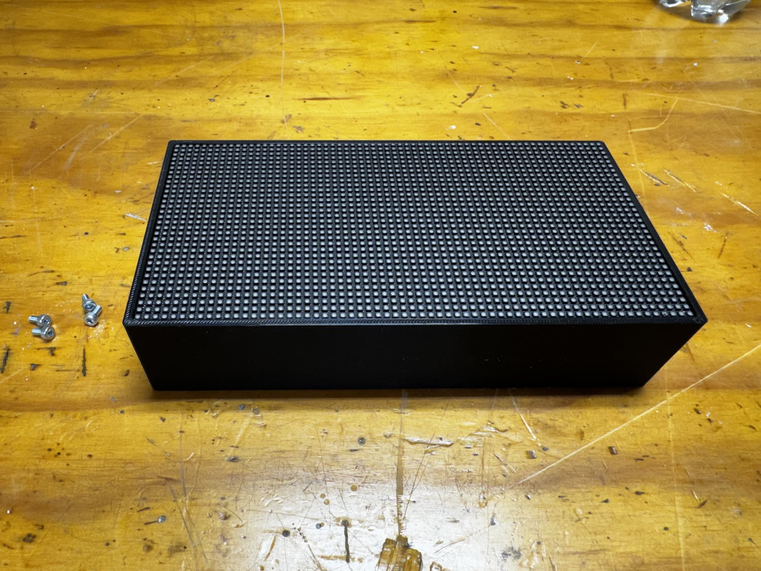
The final step: seat the LED display against the front and drive the four M3 × 6 mm cap-head screws with your hex key to secure it. That’s it. You’ve built a Theme Park Waits sign.
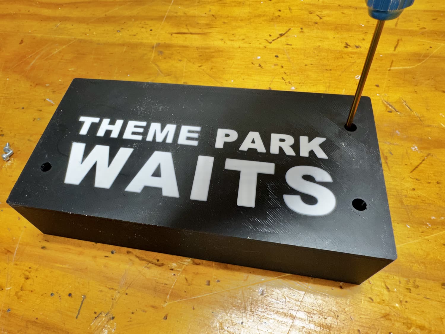

Done!
Power it over USB-C and you’re ready to bring it online. Next: flash CircuitPython, load the app, and set up WiFi from your phone.